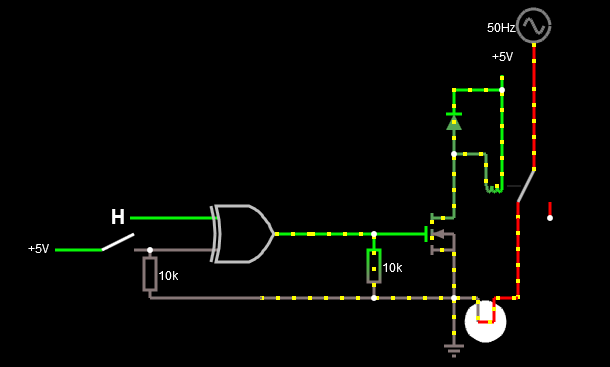
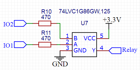
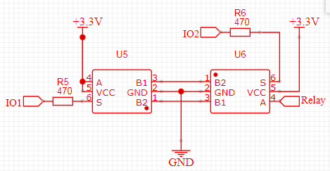
If you want a totally independent switch in case of the microcontroller fails, then you can hook-up an XOR gate for two inputs. The relay will be off when both inputs are the same, and on if the inputs are different. The two inputs are:
- Regular switch for manual control.
- Output from an MCU for automatic or remote control.
The circuit:

Normally the switch should be open (input B is low just like on the image above) and the N-FET is driven by the MCU pin. When the MCU pin is low, then the XOR gate outputs low because the inputs match(both low) and the relay will be turned off. When the MCU pin is high, the relay will be turned on because the inputs are different.
Now if the MCU crashes and its pin stucks in a state, then there are two cases:
- MCU pin stucks in high state and the relay remains turned on. In this case switch will give you an ability to control the relay as follows. If the switch is open then the relay will turned on, and if the switch is closed the relay will turned off.
- The MCU pin stucks in low state. In this case an open switch will turn off the relay and a closed will turn it on.
Here is a simulation so you can check the mechanism yourself. The GPIO pin of the MCU can be controlled remotely via Bluetooth, WiFi or the already mentioned 433 MHz module or other suitable technology.
Update requested by OP:
List of 2 inputs XOR gates available at Farnell for example. Here is a particular one from Texas Instruments also available at Farnell.
Some remarks about safety. If you decide to switch mains voltage then it is recommended to switch the hot mains wire rather than the neutral.
The best would be to use an SPDT relay to make sure and switch hot and neutral as well.

Instead of a MOSFET you could use an opto-isolator to isolate the digital circuit and the manual switch from the relay and mains.
Always use proper sealing, do not let open bare metal surfaces. Keep in my that dealing with mains voltage is always highly dangerous.


