4

I am in need to configure two UART connections from Olimex ESP32-EVB to a scanner and to a card reader.

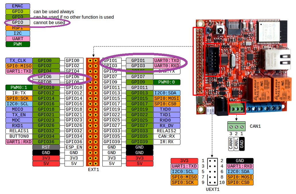
I was exploring the GPIO pins that could have helped to establish those connections, but unfortunately from what I could understand I can only use the pins GPIO04 and GPIO36 which are regarded as being UART1: TXD and UART1: RXD.

I also saw that there would seem to be a possibility for using the pins GPIO01 and GPIO03 which are documented as UART0: TXD and UART0: RXD, but these pins are marked as cannot be used.

This is troublesome for me because I cannot put the dots together on why they provide UART communication if they cannot be used?

I am attaching also the photo from which I got all this info, everything that makes me wonder is highlighted in purple ellipses.
enter image description here

1
  • did your exploration of the GPIO pins include the exploration of the schematic diagram?
    – jsotola
    Commented Jul 25, 2019 at 2:28

3 Answers 3

4

For the ESP32-EVB, most, if not all pins, are used by all of the stuff they pack on the board.

If you look at the schematic for that particular board, you'll see that UART0 (GPIO pins 1&3) are tied to the USB port.

GPIO 6,7,8,11 are tied to the SD card, that's why they are unavailable.

Schematic directory here: Github for ESP32-EVB

2

This diagram that shows the GPIO pins as not being available is out of date in my opinion. Perhaps generated from the original Rev A of this PCB.

I can see no reason why GPIO6, GPIO7, GPIO8 and GPIO11 cannot be used since PCB Rev B onwards.

On Rev A they were used for the SD Card in 4 bit mode, but since Rev B it appears that the SD card is using SPI mode and only Data0, CLK and CMD are used.

1

I’m not sure why you think you can only use GPIO 4 and 36.

Many of the pins are wired either to components on the board (e.g. SD card reader, Ethernet, serial-to-USB converter...) or just to specific ports on the board.

UART0 is the main UART used to program the ESP32, you can think of it at the “console”. It is wired to the USB-to-serial converter so you can talk to the board over USB using your usual development environment. You probably want to leave that one alone unless you really know what you are doing.

UART1 is just wired to the UEXT port. It does not even need to be an UART, this is just the convention for those two pins on the UEXT port.

IIRC the ESP32 has up to 3 UARTs, and you can assign them to any of the pins (some pins are input only though).

Likewise, GPIO 2, 14, 15, 17 are just defined as SPI because they’re wired to pins of the UEXT port which are normally used for that. If you don’t plan to connect standard UEXT devices on that port, you can reassign their roles as you want.

Same thing for GPIO 13 and 16, which are just wired to pins of the UEXT port defined as I2C.

What kind of interfaces do your scanner and card reader have? Many have a choice of several interfaces among UART, SPI or I2C, so that leaves you quite a few options. Also remember that I2C is a shared bus with addressing (so you only need one port to connect multiple devices), and SPI can in some conditions be shared as well (with separate chip select pins).

Your Answer

By clicking “Post Your Answer”, you agree to our terms of service and acknowledge you have read our privacy policy.

Not the answer you're looking for? Browse other questions tagged or ask your own question.